
dr inż. Witold Krieser
Fundamentals of robotics with Astorino
Volume I. Fundamentals of Robotics
Teacher's Manual
Introduction
Welcome, dear student, to a journey into the world of modern robotics — a fascinating field that combines mechanics, electronics, and computer science into practical and automated solutions. The book you are holding was written for those who are just starting their journey with industrial robot programming. Its main focus is the educational robot Astorino, on which all our examples are based.
Why Astorino? It is a compact, safe, and intuitive training robot that, thanks to its simplicity and flexibility, is perfectly suited for technical education – both in secondary schools and in engineering studies. At the same time, it share many characteristics with real industrial robots, making it an excellent tool for learning in a realistic environment.
Before we begin programming, we will first build a solid theoretical foundation. You will learn what a robot is, what its main features and types are, how industrial robots are classified, and how the individual components of a robotic system work. We will also cover the basic concepts of coordinate systems, kinematics, axes, motion trajectories, and safe robot operation. This knowledge forms the foundation without which it would be difficult to use the capabilities of modern robotics consciously and responsibly.
Next, we will guide you step by step through starting up and operating the Astorino robot. You will learn how to correctly connect and start up the system, use the teach pendant, how to move the robot in manual mode, and how to create your first simple programs. We have ensured that everything is clearly described and illustrated – so that you can carry out each step independently, even if you have never worked with this type of device before.
It is worth emphasizing that all materials, descriptions, and exercises in this book are directly related to the Astorino robot — wWe do not teach robotics “in the abstract,” but immediately in the context of a specific device you work with in practice. As a result, learning is not only effective but also engaging and rewarding.
Finally, we would like to note that this textbook is just the beginning. We are already working on the next volumes in the series. Volume II will be dedicated to the programming language and creating a complete programming project, e.g., a palletizing applications. Meanwhile, Volume III will introduce you to the world of integration with vision cameras, conveyors, and other peripheral devices – topics essential at an advanced level of automation.
We hope that reading this book will not only provide you with knowledge and skills, but also spark curiosity and a desire to further explore the secrets of modern robotics. Good luck!
After completing this book, you should be able to:
- explain terms related to robotics,
- identify robot applications,
- classify robots based on the structure of their kinematic unit,
- classify robots according to their application,
- describe the structure of the Astorino robot,
- explain the electrical connection interface,
- describe the technical parameters of the Astorino robot,
- use the teach pendant,
- perform simple and complex robot motions using the teach pendant,
- move the robot in different coordinate systems,
- define robot points,
- set simple and advanced robot motion sequences,
- write a program to control the robot and store it in the robot’s memory.
I. THEORETICAL ASPECTS OF ROBOTICS
1. Definitions
Manipulator – a mechanism designed to perform certain functions analogously to the human upper limb. Two types of manipulator functions should be distinguished: the manipulation function, performed by the gripper, and the positioning function, performed by the manipulator arm.
Robot Environment – the space in which the robot is located and moves. For stationary robots, the environment is limited to the workspace.
Pedipulator – the lower limb, the “leg” of a walking machine. A pedipulator can be a single- or multi-link system
HOME Position – the predefined home position of the robot. This is the point from which the robot typically begins executing a program. This point should be located in a safe place from which the robot can easily and safely start its task. For some robots, the HOME position is also a motion instruction that moves the robot to this point.
Robot joint – a movable joint between elements of the robot arm that enables rotation and gives the robot freedom of movement in space.
Cartesian Point – a point in three-dimensional space whose position is expressed using X, Y, and Z coordinates, and whose orientation can be expressed using rotation angles around the coordinate system axes.
Joint Position – a point in three-dimensional space whose position and orientation are recorded using the angular positions of the individual robot joints.
Singularities – positions of the robot in which its arm loses the ability to move in certain directions; this occurs when, as a result of adopting one of several specific positions, the robot is unable to correctly follow the specified trajectory. This phenomenon is associated with a loss of a degree of freedom caused by two joint rotation axes coinciding, making it impossible to compute the kinematics. This can lead to loss of precision, uncontrolled movements, or errors in robot operation.
Robot – a mechanical device that automatically performs certain tasks. Actions are controlled by a human operator or by an input program.
Industrial robot – an automatic, programmable multi-axis device used to perform tasks in a production environment. Its purpose is to replace or assist humans in repetitive, precise, or hazardous work. A robot should have at least three degrees of freedom and be programmable for various tasks.
Robotics – the field of science and engineering dealing with problems of mechanics, control, design, measurement, applications, and operation of robot manipulators.
Industrial robotics – the branch of robotics concerned with the use of robots to automate production processes such as welding, painting, palletizing, and assembly.
Degrees of Freedom of a Robot (DOF) – define the number of independent axes along which a robot can move. These include the X, Y, and Z axes and rotations around them, meaning that to be able to reach any point in space at any angle, a robot must have six degrees of freedom.
TCP (Tool Center Point) – a precisely defined point in space that represents the operating point of a tool mounted at the end of the robot—for example, the tip of a gripper, a welding torch electrode, a glue nozzle, or a milling cutter. The TCP is crucial because it is the reference point relative to which the robot performs movements and calculates trajectories. The position of the TCP in space is the result of forward kinematics (dependent on the positions of all axes), and when programming motions, the operator works precisely with this point. Correctly defining the TCP enables precise control of the robot’s movement in the global (base) coordinate system as well as in local coordinate systems (e.g., relative to a workpiece or a grasped object). The TCP can be thought of as the robot’s “virtual tip,” representing the actual functional point of the tool in space.
Teach Pendant – a portable control panel that enables manual programming and operation of an industrial robot. The user can use it to enter trajectory points, test movements, and monitor the robot’s status in real time. The teach pendant is directly connected to the robot controller, has compatible controls, and enables flexible work with the robot due to its mobility.
Control System – according to control theory, the task of the control system is to generate the control signal to be applied to the robot in order to achieve predefined properties.
The term “robot” first appeared in literature in 1920 in a play by the Czech writer Karel Čapek. The Czech word “robot” reffered to forced labor. Informally, robotics-related literature also introduces laws that are intended to apply to industrial robots:
Zeroth Law: A robot may not harm humanity, or, by inaction, allow humanity to come to harm.
First Law: A robot may not injure a human being, or, through inaction, allow a human being to come to harm, unless this would conflict with a higher law.
Second Law: A robot must obey the orders given by human beings unless such orders conflict with a higher law.
Third Law: A robot must protect its own existence as long as such protection does not conflict with a higher law.
Fourth Law: The richer the robot’s sensory systems, the simpler its mechanical construction can be.
2. Structure of Industrial Robots
Industrial robots consist of several basic elements, such as:
manipulator (robot arm) – it consists of joints and links that allow movement along multiple axes.
drives – electric, pneumatic, or hydraulic – they drive the robot joints.
- Electric drives – the most commonly used
,; they provide high precision and are relatively easy to control. The mainly use servo motors and stepper motors., - Pneumatic drives – used in simpler applications, especially where fast response and low forces are required.
- Hydraulic drives – characterized by high force and used where heavy loads must be handled, e.g., in welding robots in heavy industry.
- control system – responsible for the precise execution of programmed tasks, while sensors and other external devices enable the robot to respond to its environment. The control system is the “brain” of the robot – it processes information, makes decisions, and issues commands to the actuators. Modern industrial robots are controlled using programmable logic controllers (PLCs), industrial computers, or dedicated controllers.
The control system can operate in several modes:
- manual – using the teach pendant, which allows the operator to program
sthe robot’s positions and motion sequences. - automatic – after loading the program, the robot operates autonomously, executing programmed operations.
- remote or integrated – in advanced systems,
- end-effector (e.g., gripper) – also called the robot tool, this is the element mounted at the end of the robot arm that performs the specific operation – such as gripping, welding, cutting, painting, assembly, or lifting objects. The end-effector determines the robot’s application.
Types of end-effectors:
- grippers – the most common end-effectors, used for manipulating objects. The following types are distinguished:
- mechanical – equipped with jaws or mechanical fingers that clamp onto the gripped object,
- pneumatic or hydraulic – operate using air or fluid pressure, have a fast response time, used in rapid assembly,
- magnetic – for transporting metal components without the need for mechanical contact,
- vacuum grippers use vacuum to handle objects such as glass, cardboard, or plastic parts.
- process end-effectors – turn the robot into a specialized production tool, for example:
- welding torches – for automated welding,
- painting/coating
- assembly tools – e.g., automatic screwdrivers, spot welders.
- multi-function and adaptive end-effectors
- soft and adaptive grippers – can conform to the shape of an object, often used in collaborative robots (cobots),
- tactile end-effectors– integrated with force and torque sensors, enabling the robot to precisely regulate applied pressure or respond to contact.
The overall robot structure is designed to ensure speed, repeatability, and safe operation in an industrial environment.
3. Kinematic Unit of an Industrial Robot
The kinematic unit of an industrial robot is a set of mechanical elements responsible for the robot’s motion in space. It can be compared to the robot’s “skeleton” and “joints,” which enable motion in specific directions. It consists of links (rigid elements) and joints (movable connections), which together form the so-called kinematic chain. This unit defines the robot’s range of motion, the number of degrees of freedom, and its ability to perform complex tasks.
Main elements of the kinematic unit:
- Links (arms) – rigid structural segments connecting the joints. They transmit motion from one joint to the next. The length and number of links directly affect
sthe robot’s ability to execute complex trajectories. - Joints (rotation/translation axes) – locations where links can move relative to each other. Depending on the design, the following are distinguished:
- linear joints – allow movement along an axis.
A manipulator consists of links forming an open kinematic chain. Adjacent links are connected by kinematic pairs (joints). The figure below shows the kinematic structure of an anthropomorphic robot.
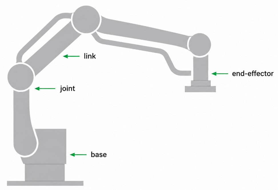
Diagram of an anthropomorphic robot
The kinematic unit of a manipulator is formed by the kinematic mechanism together with its attached drives. Modern manipulators are built as serial or sserial-parallel kinematic structures (i.e., a sequence of links and joints forming the robot’s structure), forming the so-called kinematic chain. It can be open (as in most industrial robots) or closed (as in, e.g., parallel robots).
A kinematic pair together with its associated drive enables relative motion between the connected elements, forming a drive unit. A well-designed kinematic unit determines the shape of the working area, precision, flexibility, and reach of the robot. It determines whether the robot will be able to reach a specific location, perform a task at the correct angle, and maintain appropriate dynamics and motion repeatability. Knowledge of kinematics is also crucial when programming the robot, especially in the context of solving problems of inverse kinematics (i.e., determining joint configurations so that the tool reaches the desired position and orientation).
Knowledge of kinematics allows us to determine the number of degrees of freedom of a robot, i.e., the number of independent movements the robot can perform. A standard industrial robot typically has 6 degrees of freedom – three translational (motion along the X, Y, Z axes) and three rotational (rotations around these axes, i.e., RX, RY, RZ), allowing full control of the end-effector’s position and orientation. Other important parameters describing industrial robots are accuracy and repeatability. The Aaccuracy of the robot determines how close the manipulator can reach to a specified point in the working space. Repeatability (e.g., +/- 0.2 mm for the Astorino robot, or +/- 0.03 mm (!) for the Kawasaki RS007L robot) is a measure of how close the manipulator can return to a previously reached position.
The following concepts are related to robot kinematics:
- Forward kinematics (forward transformation) – determines the position of the end-effector for a given joint configuration. The forward kinematics problem always has exactly one solution.
- Inverse kinematics (inverse transformation) – determines the joint configuration required to achieve a given end-effector position. It may have a varying number of solutions obtained algebraically, geometrically, or numerically. To simplify the mathematical description of mechanical arm connections, the so-called Denavit-Hartenberg convention has been introduced in robotics. It allows for a smooth transition from the beginning to the end of a kinematic system, provided that its joints have exactly one degree of freedom each.
4. Robot Classification
Classifying industrial robots allows us to understand their diversity and find the right type of robot for a specific application. The choice of an appropriate robot depends, among other things, on the tasks it is to perform, the working environment, required accuracy, speed, and the ability to integrate with other elements of the production system. Depending on their structure, mode of operation, and intended use, industrial robots can be divided into various classes and types.
GOOD TO KNOW AND REMEMBER: An industrial robot must above all be safely integrated into the environment in which it operates. Safety is one of the most important aspects of working with a robot, and it is important to consider safety from the very beginning. In addition, an industrial robot must have a structure that enables it to perform its task at the workstation as optimally as possible.
Robot Classification by Kinematic Structure
The kinematic structure of a robot, i.e., the arrangement of its joints and links, affects the range of motion, accuracy, reach, and possible applications of robots. The following types of robots are distinguished:
- Cartesian Robots (XYZ)
- They move along three linear axes (perpendicular to each other – like the coordinate axes of a Cartesian system).
- They are characterized by a simple structure and high rigidity.
- Applications: packaging, palletizing, cutting, milling.
- Cylindrical Robots
- They perform linear motion along vertical and horizontal axes, and rotational movement around the vertical axis.
- Used in part assembly and machine tending.
- Spherical Robots
- They combine rotational and linear movements, enabling work in a space resembling a spherical sector.
- Their main advantage is a large reach with a compact design.
- SCARA Robots
- They move along two horizontal axes and one vertical axis. They have 3 degrees of freedom.
- They are characterized by high speed and rigidity along the vertical axis.
- Ideal for assembling parts or PCBs, transferring light components, and screwing.
- Anthropomorphic Robots
- They have 6 degrees of freedom, providing maximum flexibility.
- Their movement resembles the movement of a human arm.
- Widely used in welding, painting, assembly, and manipulation.
- In practice, these are the most commonly used robots.
- Delta Robots
- They have a parallel structure and are very fast and lightweight.
- Designed for sorting, packaging, and manipulating light objects.
- Used mainly in the food, electronics, and cosmetics industries.
Classification by Application Type
Industrial robots can also be classified according to the functions they perform in the production process:
- Welding Robots
- They perform precise welds (MIG/MAG, TIG, spot).
- They are equipped with welding end-effectors, arc sensors, and weld quality control systems.
- Used in the automotive, machinery, and construction industries.
- Assembly Robots
- They are characterized by high precision; often they are SCARA or delta robots.
- They are used for assembling electronic components and mechanical devices.
- They work together with vision systems and force sensors.
- Material Handling Robots
- Versatile robots for transferring, arranging, and sorting.
- They can work with grippers and transport systems.
- Depending on the application, these robots can also be equipped with other end-effectors, such as welding torches.. The available configurations depend on the manufacturer and the specific robot model..
- Painting Robots
- Equipped with spray guns, adapted for precise application of paints.
- They work in spray booths, often in explosive environments.
- Machine Tending Robots
- They transfer parts between the robot and the machine tool (e.g., lathe, milling machine).
- They automate CNC stations, injection molding machines, and presses.
- Palletizing and Depalletizing Robots
- They facilitate and speed up packaging and stacking goods on pallets.
- Used in logistics, food, and construction industries.
- They are often characterized by a simplified structure – e.g., 4 degrees of freedom – which allows for faster trajectory calculations and minimizes the risk of kinematic singularities.
- They perform tasks along a precisely defined motion path.
Classification by Control Type
Position-Programmed Robots
- The operator specifies specific positions that the robot memorizes.
- Programming is done using the teach pendant.
Adaptive Robots
- They can respond to changing environmental conditions thanks to sensors and control algorithms.
- Example: robots working with vision systems.
Autonomous Robots
- They make decisions independently based on sensor data and artificial intelligence.
- They are part of advanced Industry 4.0 production systems.
Classification by Type of Human Collaboration
Conventional Industrial Robots
- Separated from humans by guards and safety barriers.
- They work in enclosed work zones.
Collaborative Robots (Cobots)
- Adapted for direct work with humans without the need for physical safety barriers (unless required by the end-effector and the workpiece).
- Equipped with force sensors, safety systems, and a user-friendly interface.
- Lighter and more flexible, though often with lower payload capacity.
- Slower than industrial robots and less popular.
Classification by Degree of Mobility
Stationary Robots
- Permanently mounted to the floor or structure.
- Most commonly found on production lines.
Mobile Robots (AMR)
- Capable of autonomous navigation through production facilities and warehouses.
- Used for transporting components, tools, and goods.
- Often work together with a robotic arm.
5. Technical Parameters of Industrial Robots
Industrial robots differ from each other in their structure, purpose, and control method. Their capabilities are described by a set of technical parameters that allow assessment of whether a given robot is suitable for a specific task in a production facility.
Selecting an industrial robot involves more than choosing a manufacturer; it requires careful analysis of its technical parameters. Each parameter directly affects safety, efficiency, accuracy, and operating costs. Understanding these values is the key to successful production automation.
- Number of Degrees of Freedom – indicates the number of independent movements the robot can perform.
- Working Range – the maximum distance from the robot base that the end-effector can reach (excluding dead zones).
- Payload – the maximum mass the robot can handle at full reach while maintaining accuracy and safety.
- Repeatability – the accuracy with which the robot can return to a previously programmed position.
- Working Speed – determines how quickly the robot can execute motion (e.g., in degrees/second for rotary axes or mm/s for linear axes).
- Range of Motion for Each Axis – for each robot axis, a range of motion is defined (e.g., ±180° for a rotary axis, 0–700 mm for a linear axis).
- Robot Weight – the total weight of the robot without the end-effector and additional accessories.
- Cycle Time – time to complete a standard task (e.g., moving from point A to point B and back).
- Power Supply and Power Consumption – information about the type of power supply (e.g., 230 V AC, 400 V, three-phase) and energy consumption (kW).
- Communication Interfaces – protocols through which the robot communicates with other devices (e.g., Ethernet/IP, Profinet, Modbus, RS232).
- Operating Environment (operating temperature, permissible humidity, pressure, etc.).
Mounting Options:
- mounting on a stable floor (most common),
- wall or ceiling mounting,
- mounting in the so-called inverted configuration (for spatial applications).
- Compatibility with End-Effectors and Sensors
Programming Method:
- Using a teach pendant (in ”teach” mode),
- Offline programming (e.g., using CAD/CAM software),
- Graphical block-based programming (for beginners),
- Using a text-based programming language (e.g., AS language).
6. Safety When Working with a Robot
Safety when working with industrial robots is one of the most important aspects of implementing automation in production facilities. Although robots increase efficiency and precision, they can also pose serious hazards to human health and life. For this reason, health and safety regulations, technical standards, and appropriate procedures are indispensable in designing, commissioning, and operating robotic workstations.
Safety involves design, technical, and human aspects. Every robotic system must be well designed, properly secured and operated by competent personnel. Only then is it possible to fully utilize the potential of robots while maintaining the highest level of occupational safety.
During robot operation, the following hazards can be identified, arising from:
- rapid robot arm movement may strike the operator,
- high payload – the carried load may fall or be released,
- sharp tools – e.g., in welding, cutting, or adhesive applications,
- lack of awareness of its surroundings– the robot does not “see” a human unless it is equipped with appropriate sensors.
Additionally, hazards may arise from:
- programming errors (e.g., incorrect trajectory),
- technical failure (e.g., motor stop, cable breakage),
- unauthorized interference with robot operation.
- workstation conditions.
Therefore, a very important aspect of working with an industrial robot is implementing appropriate technical safety measures against potential hazards:
Fencing and Physical Barriers
- Used to separate the robot’s work zone from unauthorized access.
- Example: Steel fencing or acoustic barriers.
Gates and Emergency Stops
- Entering a work zone protected by a light curtain, pressure-sensitive mat, or radar should automatically stop the robot.
- Every workstation should have an easily accessible emergency STOP button – such circuits directly cut power to the robot, preventing safeguards from being bypassed through software.
Safety Light Curtains and Scanners
- Emit light beams – if interrupted, the robot immediately stops. They allow dynamic monitoring of human presence in the vicinity.
Mechanical Guards
- Protect against spatter, sparks, or moving tool parts.
- In welding applications, protective viewing panels are used that allow observation of robot’s operation while blocking harmful radiation.
- Other safeguards are also used, such as limit switches that only allow the robot cycle to start when the safety enclosure doors are closed.
Robotic workstations are designed with important safety standards in mind. These standards define requirements for safe design and protective measures when working with industrial robots and integrating robotic systems. Key standards compliant with Machinery Directive 2006/42/EC are:
- EN ISO 10218-1:2011 – relates to the safety of industrial robots.
- EN ISO 10218-2:2011 – relates to the safety of the robot system and its integration.
Additionally, other standards related to the safe design of machines, electrical systems, and control systems are used, such as:
- PN-EN ISO 12100:2012 – contains general principles for machine design and risk assessment and reduction.
- PN-EN 62061:2008/A1:2013-06 – relates to the functional safety of electrical and electronic control systems.
- PN-EN 13849-1:2016-02 – relates to safety-related parts of control systems.
CHECK YOUR KNOWLEDGE
Open Questions:
1. What is the definition of an industrial robot?
Answer: An industrial robot is an automatically controlled, programmable, multi-purpose unit operating in three or more axes, intended for industrial applications.
2. Name three fields from which robotics originates.
Answer: Mechanics, automation, and computer science.
3. What features should an industrial robot have to be called a robot?
Answer: A robot should be automatically controlled, programmable, multi-purpose, and have at least three axes of motion.
4. Give examples of industrial robot applications in a factory.
Answer: Welding, painting, palletizing, assembly, packaging, material transfer.
5. Explain the difference between a robot and a CNC machine.
Answer: A robot is more flexible and versatile – it can perform many different tasks through programming. A CNC machine performs specific machining operations, such as milling or turning, according to a given program.
6. How does a Cartesian robot differ from an anthropomorphic robot?
Answer: A Cartesian robot moves along straight X, Y, and Z axes, while an articulated robot has movable joints that allow it to perform more complex spatial movements.
7. What are the main benefits of using industrial robots?
Answer: Increased productivity, repeatability, precision, reduced labor costs, safety in hazardous conditions.
8. What does the programmability of a robot mean?
Answer: The ability to change the robot’s tasks by editing the program without requiring mechanical modifications.
9. How does a robot execute commands?
Answer: A robot executes commands through a programmed sequence of instructions that control its movements and actions via the control system.
10. Why must industrial robots have at least three axes?
Answer: So that they can move in three-dimensional space – along the X, Y, and Z axes.
11. How does a teach pendant differ from a conventional control computer?
Answer: A teach pendant is a special panel for manual robot control, used for programming and testing motion directly at the robot.
12. What structural types of industrial robots do you know? Name at least two.
Answer: Cartesian, cylindrical, spherical, SCARA, articulated (anthropomorphic), delta.
13. How does a robot „learn” a task?
Answer: By programming trajectories and actions – manually or using the teach function.
14. What elements make up an industrial robot?
Answer: Manipulator (robot arm), controller, teach pendant, drives, sensors, end-effector (work tool).
15. What does „end-effector” mean? Provide an example.
Answer: An end-effector is the tool mounted at the end of the robot arm that performs the task – e.g., a gripper, welding torch, or paint nozzle.
16. Why is safety when working with a robot so important?
Answer: Because the robot operates with high speeds and significant forces – careless operation can lead to serious accidents.
17. Can a robot replace a human in every type of work? Justify your answer.
Answer: No – robots are good at repetitive and precise tasks, but do not cope well with non-standard situations or creative work.
18. What does the term “degrees of freedom” mean in the context of robot design?
Answer: Degrees of freedom (DoF) indicate the number of independent directions of motions in which the robot can move. Each axis or joint of the robot adds one degree of freedom.
19. How do industrial robots affect production efficiency and quality?
Answer: Industrial robots increase production efficiency thanks to their speed, repeatability, and ability to work 24/7 without breaks. They also standardize production processes, resulting in higher product quality and fewer errors, while enabling precise operations that would be difficult or hazardous for humans. In the long term, robotization can reduce production costs and improve a company’s competitiveness.
Test Questions:
Multiple Choice Test – Basic Level
1. Which of the following best describes the definition of an industrial robot?
A. A machine that performs only one action.
B. An automatically controlled, programmable, multi-purpose industrial device with at least three axes.
C. An agricultural machine used in industry.
D. A person controlling a machine remotely.
2. How many degrees of freedom should a robot have to move in three-dimensional space?
A. 2
B. 3
C. 4
D. 6
3. Which type of robot moves along the X, Y, and Z axes using prismatic (sliding) joints?
A. SCARA
B. Cartesian
C. Anthropomorphic
D. Delta
4. Which sentence best describes a teach pendant?
A. A robot cooling device
B. A computer program
C. A manual robot control and programming panel
D. The gripping part of the robot
5. What is an „end-effector”?
A. The robot’s control unit
B. The robot’s power supply
C. The tool mounted at the end of the robot arm
D. The robot’s chassis
6. Which of the following robots most closely resembles a human arm?
A. SCARA
B. delta
C. Cartesian
D. articulated robot
7. Why are industrial robots used in industry?
A. They are cheap to purchase
B. They replace CNC machines
C. They increase efficiency, precision, and safety
D. They require no maintenance
8. Which task is most commonly performed by robots in the automotive industry?
A. painting walls
B. welding car bodies
C. cutting paper
D. pressure measurement
9. Which of the following statements is true?
A. robots always work faster than humans
B. robots do not get tired and perform tasks repetitively
C. robots can make ethical decisions
D. robots do not require programming
10. Why can students safely learn on the Astorino educational robot?
A. It is fast and powerful
B. It requires specialized clothing
C. It is compact, safe, and easy to operate
D. It has a steel casing
Practical Tasks:
1. Task: Robot Classification
Instructions: Find any industrial robot on the Internet or in a manufacturer’s catalogue. Then:
– Identify its type (e.g., Cartesian, SCARA, anthropomorphic).
– State the number of axes, their type, and orientation.
– Describe its basic application.
Outcome: A short write-up (e.g., 5–6 sentences) including the robot’s name and a photo.
2. Task: Description of the Kinematic Unit
Instructions: Draw a simplified diagram of an industrial robot (e.g., anthropomorphic) and label its main axes and links.
Outcome: Drawing + labels: axes, links, joints.
3. Task: Identification of Robot Elements
Instructions: Based on the robot structure diagram (provided by the teacher or from the book), name its main elements: manipulator, controller, end-effector, teach pendant, sensors.
Outcome: Completed table or labelled drawing.
4. Task: Comparison of Robot Applications
Instructions: List 3 different industries in which industrial robots are used. For each one, give an example of a specific task performed by a robot.
Outcome: Table: Industry – Task – Robot Type (if known).
5. Task: Benefits and Limitations of Robotization
Instructions: Write a short analysis (5–6 sentences) on the main benefits of using robots in production and discuss their limitations.
Outcome: Text containing at least 3 benefits and 3 limitations.
6. Task: Robot Workstation Simulation
Instructions: Using simple materials (e.g., boxes, blocks, paper), design a model of a robot workstation performing a simple task (e.g., transferring a part). Describe the role of each workstation element.
Outcome: Physical model or drawing + brief description of operation.
7. Task: Robot Trajectory Analysis
Instructions: Based on the attached robot diagram, determine the trajectory the robot should follow on the assumption that it must move from point A to point B. Identify the type of robot motion:
– linear motion,
– curved motion,
– complex motion (e.g., a figure-eight trajectory)
Outcome: Trajectory drawing and a short description (e.g., which axes are involved in the motion, what kinematic changes are required).
8. Task: Palletizing Task Simulation
Instructions: Assume you have a palletizing task in which the robot must transfer products from a conveyor and arrange them on a pallet in a specified manner.
– Determine the minimum number of degrees of freedom the robot should have to effectively perform this task.
– What sensors may be helpful in this process?
– What algorithms can support the precise placement of products?
Outcome: A short description of the task solution.
II. THE ASTORINO ROBOT
1. General Information about the Astorino Robot
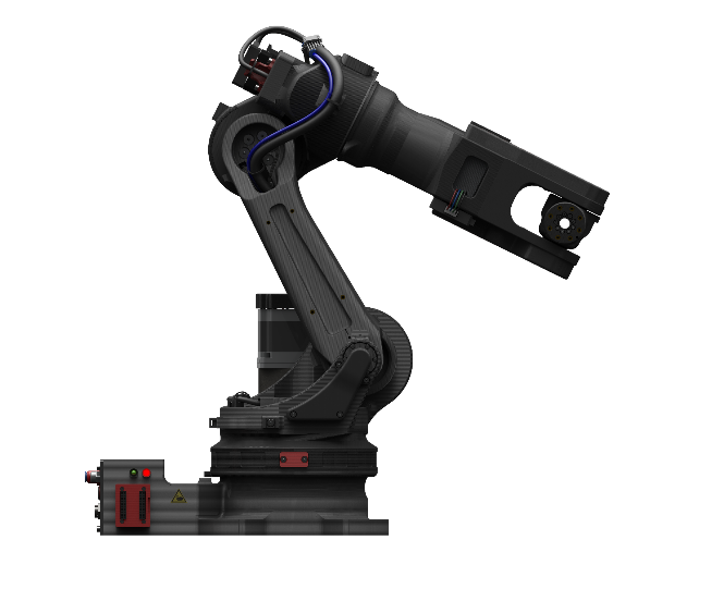
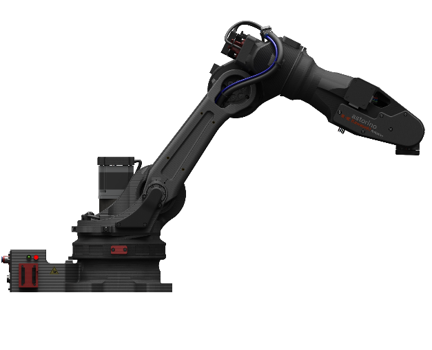
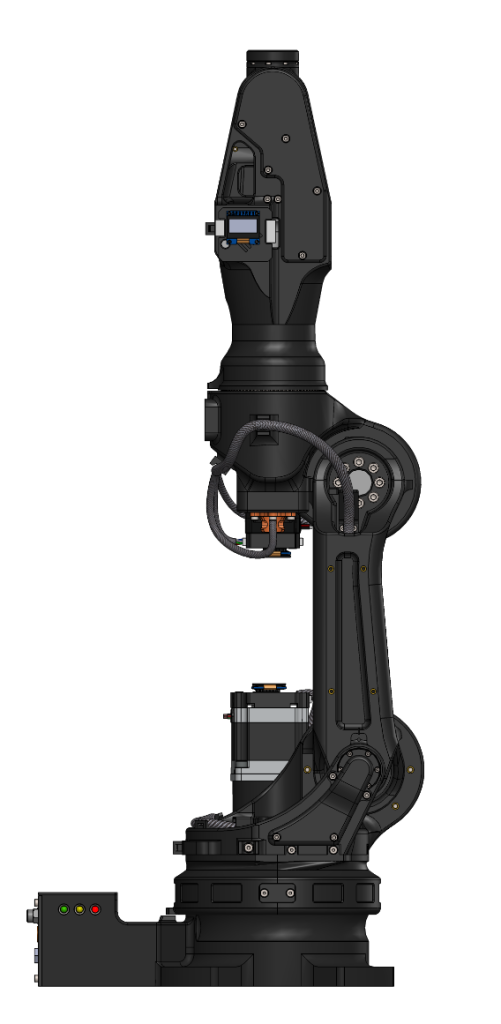
Astorino Kawasaki is a 6-axis educational robot developed specifically for training institutions. Students can use the Astorino to learn about automation and robotization of industrial processes in practice.
The robot’s construction is based on 3D printing using a special carbon-fiber filament. Programming and control are performed using the Astorino software. Like Kawasaki industrial robots, the Astorino robot is programmed in the AS language, enabling users to learn programming for real industrial applications.
Astorino Robots are designed for moving and positioning small loads or objects. They are intended for educational use in a controlled laboratory environment.
Basic Parameters:
- 6 degrees of freedom,
- Constructed using 3D printing technology,
- Steel gears with reduced backlash,
- Programming in a simplified version of the AS language,
- Stepper motors operating in a closed-loop control system,
- Axis homing required after power-off due to the absence of absolute encoders,
- STL files available after purchase for printing replacement parts,
- Non-volatile memory – all user data is retained after power loss.
Technical Specifications:
- Gears backlash: <3 arcmin,
- Repeatability: +/-0.2 mm,
- Material: PET-G filament – readily available,
- Steel crown bearing on the first axis,
- CPU 600 MHz,
- Hollow wrist and axes 4 and 6,
- I/O 8x 3.3 V (5 V tolerant),
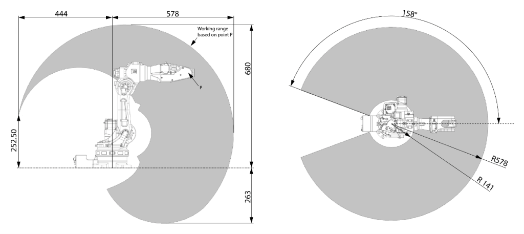
- Reach: 570 mm,
- Nominal payload: 1 kg,
- Communication protocols: Modbus TCP, serial communication, TCP/IP, and UDP,
- E-STOP 24 V galvanically isolated inputs – 2 channels,
- Safety fence: 24 V galvanically isolated inputs – 2 channels (option),
- Accelerometer-based collision detection – robot motion stops upon impact detection,
- 2x 24 V PNP inputs and 2x 24 V PNP outputs on the arm via 6-pin XH-2.54 connector,
- Ability to connect two external encoders.
Arm Parameters:
| axis | range | speed [°/s] |
| JT1 | -158.5÷158.5 | 40 |
| JT2 | -90.0÷127.0 | 32 |
| JT3 | 0.0÷159.5 | 32 |
| JT4 | -240.0÷240.0 | 140.5 |
| JT5 | -120.0÷120.0 | 127.5 |
| JT6 | -360.0÷360.0 | 216 |
Reach:
Expansion Options:
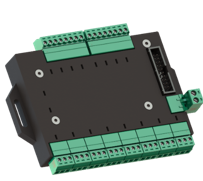
24V I/O Module
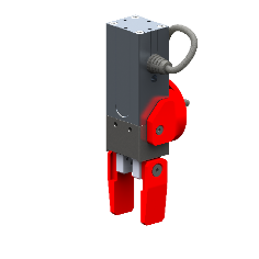
Electric gripper
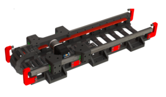
Linear track as 7th axis
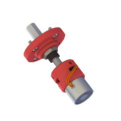
Magnetic gripper
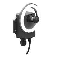
Vision system based on OpenMV
(programmable in MicroPython)
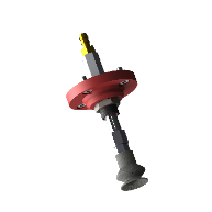
Vacuum gripper
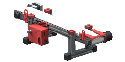
Conveyor belt
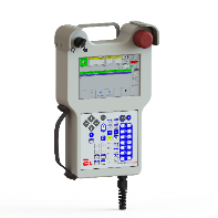
Teach pendant
Mounting plate
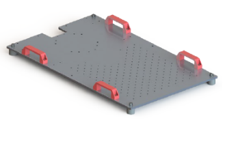
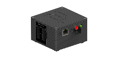
SimBox
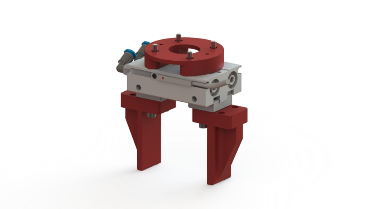
Pneumatic gripper
Cube feeder
2. Robot Motion – Interpolation
n industrial robotics, what matters is not only where the robot moves to, but also how it gets there. The path followed by the robot arm between two points is determined by interpolation – i.e., the method used to define the robot’s motion trajectory. An industrial robot can perform different types of motion depending on the task – e.g., welding, assembly, palletizing, or material transfer. In practice, three basic types of interpolation are most commonly used: joint, linear, and circular.
- Joint Interpolation
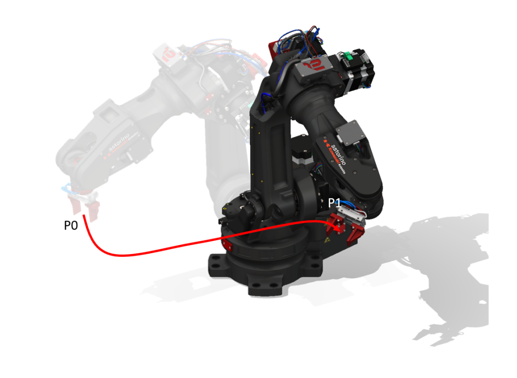
In this mode, each robot joint moves independently, at its own speed and range of motion, so that the tool tip (TCP) reaches the target point. The TCP trajectory is not controlled – it can take any shape.
Characteristics:
- Fast and natural robot motion.
- No control over the TCP path – it may follow an unpredictable trajectory.
Applications:
- Material handling,
- Positioning between operations,
- Point-to-point movements without obstacles.
Example using the Astorino robot:
Robot moves from position A to position B, lifting a part – we do not control exactly how it moves; it simply needs to reach the target.
In this type of interpolation, the robot moves from its current position to the target position in such a way that all axes finish the movement at the same time. This motion creates an unpredictable TCP path in 3D space. This motion helps avoid the problem of moving through singular points.
- Linear Interpolation
In this mode, the robot moves in a straight line between two points, and its tip maintains constant speed and an accurate trajectory. All robot axes work simultaneously to maintain linear tool motion.
Characteristics:
- The TCP trajectory is straight and precise.
- It enables obstacle avoidance and precise tool guidance.
- The motion is smooth but slower than joint interpolation.
- It should be noted that this motion is limited by the robot’s workspace limits and is susceptible to singularities.
Applications:
- Gluing, linear welding,
- Precision assembly,
- Guiding the tool along a line.
Example from the Astorino robot:
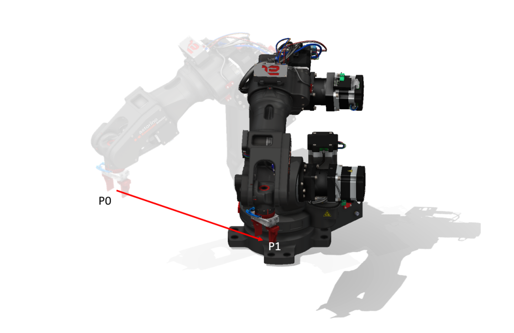
The robot guides the glue nozzle from point A to B along a straight line to apply an even bead of glue to a housing component.
In this type of interpolation, the robot moves from its current position to the target position in such a way that the TCP moves in a straight line in 3D space.
- Circular Interpolation
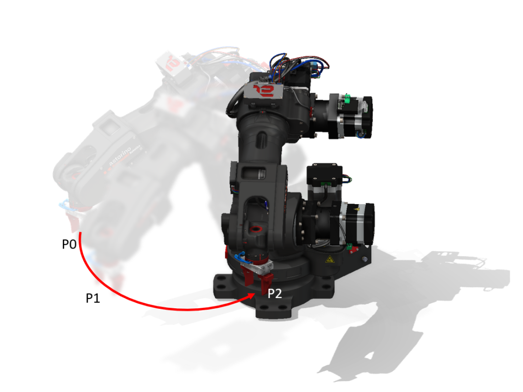
In this mode, the robot moves along an arc, i.e., along a portion of a circle. It requires specifying at least three points: a start point, an intermediate point (on the arc), and an end point. The tool tip trajectory follows a precisely defined arc.
Characteristics:
- Motion along a precise curve (portion of a circle).
- Used where it is necessary to follow curved shapes.
- Requires more precise programming than linear motion.
Applications:
- Welding and painting curved edges,
- Polishing and cleaning rounded surfaces,
- Circumferential motion.
Example using the Astorino robot:
The robot simulates welding the edge of a semicircular pipe, moving smoothly along an arc from point A through B to C.
In this type of motion, the robot moves from its current position to the target position via an intermediate point in such a way that the TCP traces an arc in 3D space.
Each type of interpolation has a different application depending on the task. Choosing the appropriate mode affects accuracy, safety and robot efficiency. A well-programmed motion not only speeds up operations but also prevents collisions and errors in the production process.
Example helpful instructions:
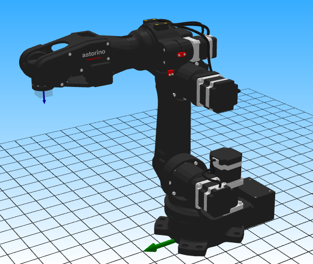
- HOME – a joint-interpolated motion (may follow an unpredictable path) moves the robot to the predefined HOME position. The default home position is shown in the figure below. The HOME position can be changed from the default, but this is not recommended.
- LAPPRO point, distance – a linear interpolation motion type characterized by the fact that, in addition to the target point in space, it takes as an argument the distance at which the robot should stop relative to the Z-axis of the active tool. Example: “LAPPRO P5, 20”, meaning the robot approaches a point located 20 mm away along the tool’s Z-axis. This motion command is particularly important for safely approaching a target, such as a workpiece on a conveyor belt.
- JAPPRO point, distance – a motion similar to LAPPRO but using joint interpolation.
- LDEPART distance – linear withdrawal from the current position by a specified distance along the active tool’s Z axis.
- JDEPART distance– similar to the motion above, but using joint interpolation.
3. Robot Coordinate Systems
Coordinate systems are one of the fundamental topics in industrial robotics. They allow precise determination of the position and orientation of robot elements, tools, and objects in the robot’s surroundings. In short: the robot does not “see” the world like a human does – it represents everything in terms of numbers and angles, with reference to adopted coordinate systems.
A coordinate system is simply a way of describing the position of a point in space. In robotics, the most commonly used is the 3D Cartesian coordinate system, consisting of three axes. For Astorino:
- X – horizontal axis (left/right movement),
- Y – transverse axis (front/back movement),
- Z – vertical axis (up/down movement).
Additionally, to describe orientation (i.e., “how the robot is rotated”), three rotation angles are required, usually denoted as:
- Rx – rotation around the X axis,
- Ry – rotation around the Y axis,
- Rz – rotation around the Z axis.
This method of describing is referred to as the TCP position and orientation ( Tool Center Point).
An industrial robot has several different coordinate systems that work together. Here are the most important ones:
- Base Coordinate System
This is the robot’s main coordinate system, fixed at its base. All other reference frames can be defined relative to it.
- The point (0,0,0) is usually located at the center of the robot’s base.
- The X, Y, Z axes are factory-set and fixed – the Z axis is typically directed vertically upward, the X axis left/right, and the Y axis front/back.
For the Astorino robot, the axis configuration is as follows:
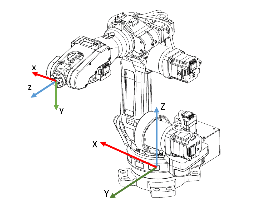
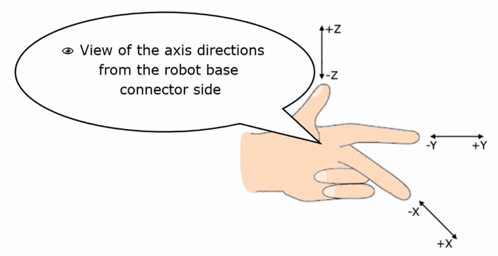
The left-hand rule helps remember the axis directions:
- Joint Coordinate System
This is a way of describing the robot’s position not through its tip (TCP), but using the joint angles. It allows individual control of each robot axis according to the positive or negative direction of each joint. Positions are usually expressed in degrees (°), referring to joint angles. This is ideal for tasks requiring precise control of individual joint movements.
- Used in joint interpolation (JMOVE in the case of Astorino).
- This is the robot’s natural motion mode, since the robot calculates its position in Cartesian space based on joint positions.
- Important in diagnostics and trajectory programming.
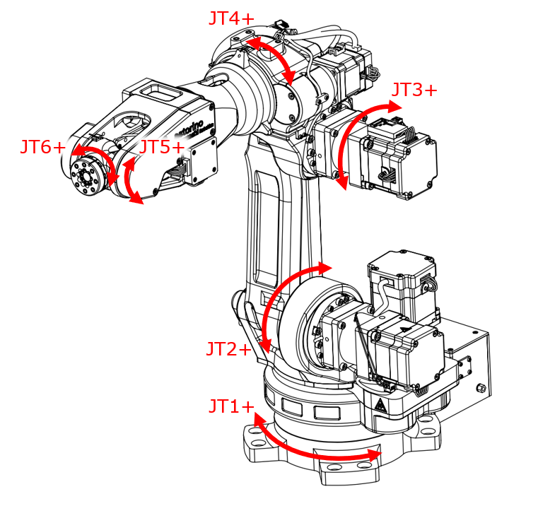
The joints are numbered consecutively, starting from the robot base. JT stands for axis.
JT = axis
- Tool Coordinate System
This is a coordinate system attached to the robot tool, e.g., a gripper or welding nozzle. It changes dynamically as the arm moves.
- The point (0,0,0) is the so-called TCP – the center of the tool oriented so that the direction and rotation of the Z axis is perpendicular to the robot’s flange, or to the TCP point defined at the tool tip. This means that motion along the Z axis moves the robot in the tool’s approach direction, allowing, e.g., easy picking of products from feeders or entering a tool into a machine.
- Essential for precise applications, e.g., gluing or cutting.
- Work Coordinate System
This is a coordinate system that the user can define themselves – e.g., relative to an assembly table, pallet, or workpiece. This simplifies programming, because instead of thinking globally (using points defined relative to the robot’s base), we operate locally (using points defined, e.g., relative to the edge of a pallet). It can be set, e.g., at the corner of a pallet with products.
- It allows easy shifting and recalculation of the entire robot program if the workstation location changes, since it is sufficient to redefine the origin of the work coordinate system.
Particularly useful in palletizing, assembly, and machine tending.
Every robot motion must be carefully planned – not only where it needs to go, but also by which path, with what orientation, and relative to what.
Proper use of coordinate systems allows:
- more flexible and reusable programming,
- easier adaptation of programs to changes in the environment (e.g., a shifted pallet),
- avoiding errors and collisions – e.g., the tool can always be positioned at the correct angle relative to the workpiece.
4. Robot Operating Modes
Industrial robots and the Astorino educational robots operate in two basic operating modes: Teach and Repeat. Understanding them is essential for programming and operating robots.
- Teach Mode – Teaching the Robot
This mode allows the operator to manually move and teach the robot. In this mode, the maximum speed is limited to 60 mm/s and 12 °/s for each axis. Teaching refers to programming the robot to perform specific tasks and recording position data. In this mode, it is possible to:
- move the robot arm in space: in Cartesian systems (base, tool, work) or in joint mode,
- save specific positions as program points (e.g., start, gripping, placing),
- test motion trajectories,
- edit or correcting existing programs.
Teach mode is intentionally slow to ensure safe operator control. This is the mode in which robots are programmed step by step.
Moving the Robot in Manual Mode (Teach)
Select the coordinate system:
- BASE (base coordinates)
- TOOL (tool coordinates)
- JOINT (single-axis mode)
- CONV (synchronous in combination with an optional external encoder – conveyor)
- WORK (WORK coordinate system)
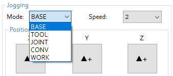
Setting the robot speed
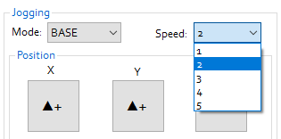
“▲+” and “▼-” move the robot in teaching mode at the selected speed:
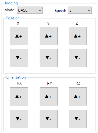
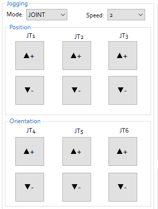
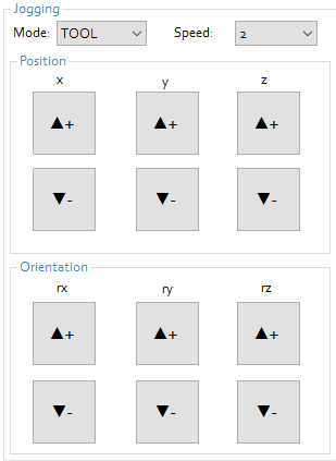
- BASE (Cartesian coordinates): X, Y, Z, RX, RY, RZ
- TOOL (Cartesian coordinates): x, y, z, rx, ry, rz
- JOINT (single axis): JT1, JT2, JT3, JT4, JT5, JT6
If the selected speed is set to 1 (step), pressing the JOG buttons (+/-) causes the robot to perform a single incremental movement. Incremental motion is configured in the STEP-TEACH section.
JT1: Left and right rotation of the arm
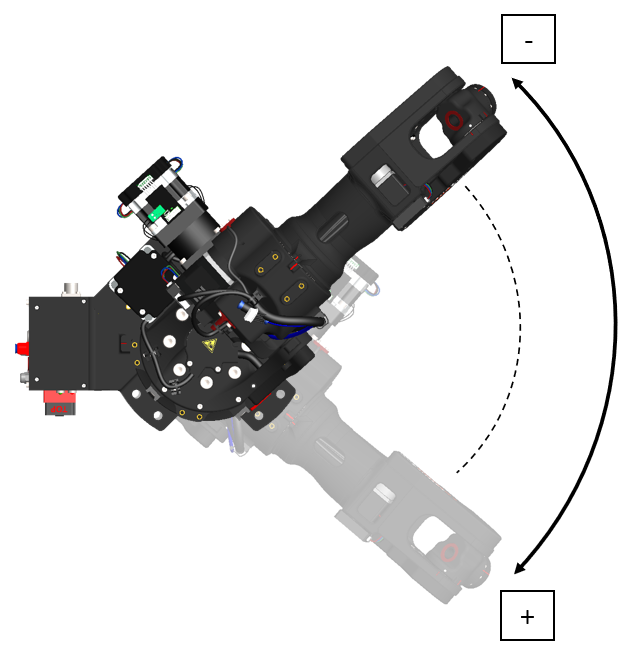
Moving the robot in manual mode (Teach). In Teach mode, the robot arm can be moved manually using the teach pendant or a dedicated computer application. The movement is performed according to the selected coordinate system (Base, Joint, or Tool).
- JOINT (Joint Motion)
JT1: Left and right rotation of the arm
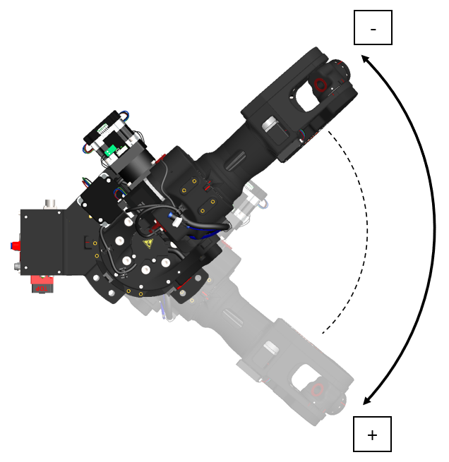
JT2: Forward and backward arm movement
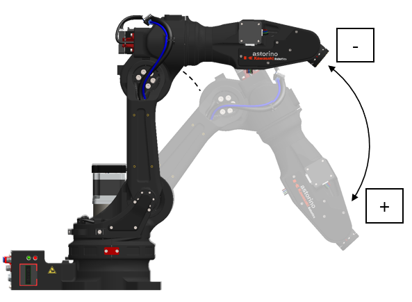
JT3: Upward and downward arm movement
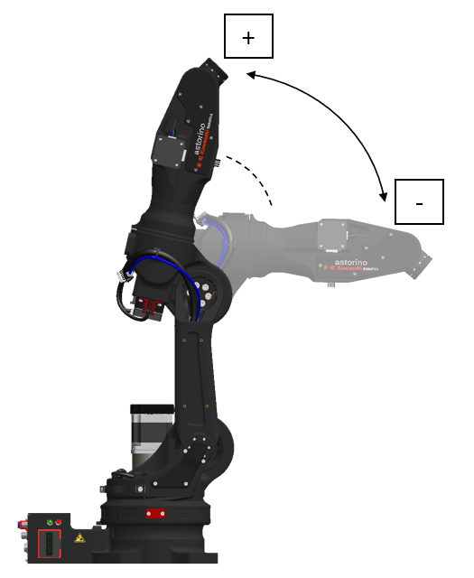
JT4: Wrist axis rotation (1)
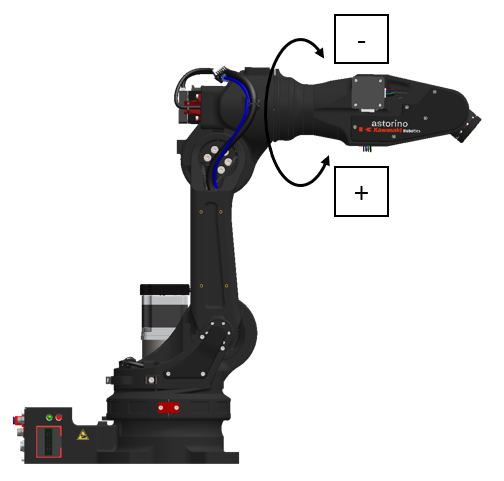
JT5: Wrist axis rotation (2)
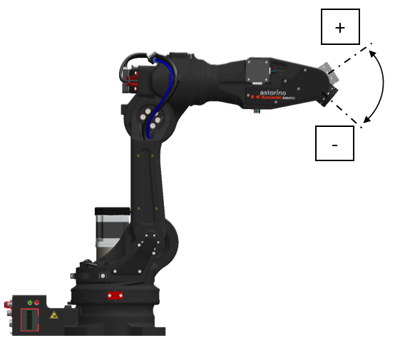
JT6: Wrist axis rotation (3)
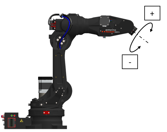
- BASE (Motion relative to the base coordinate system)
X: Motion parallel to base coordinate X (wrist orientation is fixed)
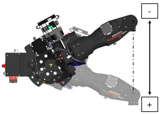
Y: Motion parallel to base coordinate Y (wrist orientation is fixed)
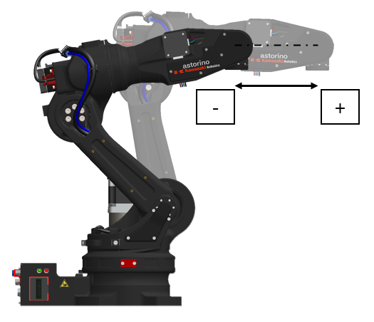
Z: Motion parallel to base coordinate Z (wrist orientation is fixed)
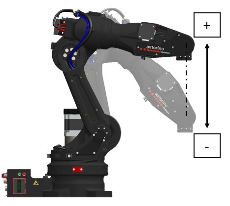
RX: Rotation around coordinate X (TCP does not move)
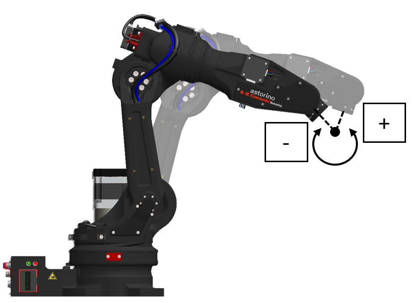
RY: Rotation around coordinate Y (TCP does not move)

RZ: Rotation around coordinate Z (TCP does not move)
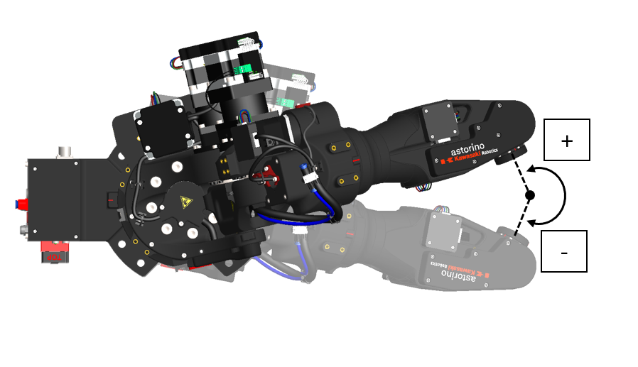
- TOOL (Motion relative to the tool coordinate system)
The tool coordinate system is defined relative to the tool mounted on axis 6. Operations based on this tool coordinate system will differ in motion direction depending on the coordinate transformation relative to the null (zero) tool frame. The tool coordinates also change as the wrist orientation changes, as shown in the figures below, even though only the forearm moves without moving the wrist axes.
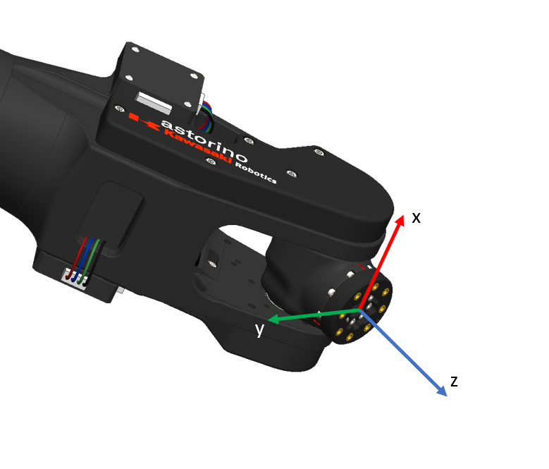
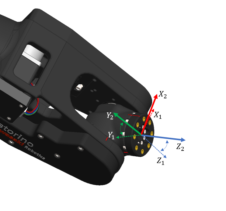
x: Motion parallel to tool coordinate X (wrist orientation is fixed)
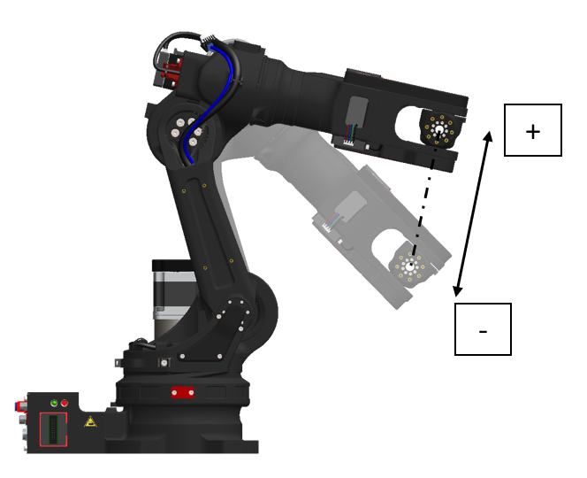
y: Motion parallel to tool coordinate Y (wrist orientation is fixed)
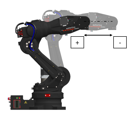
z: Motion parallel to tool coordinate Z (wrist orientation is fixed)
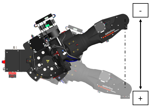
rx: Rotation around tool coordinate X (TCP does not move)
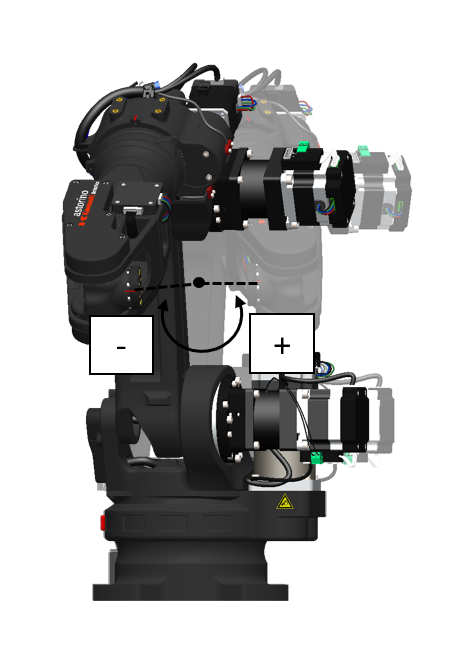
ry: Rotation around tool coordinate Y (TCP does not move)
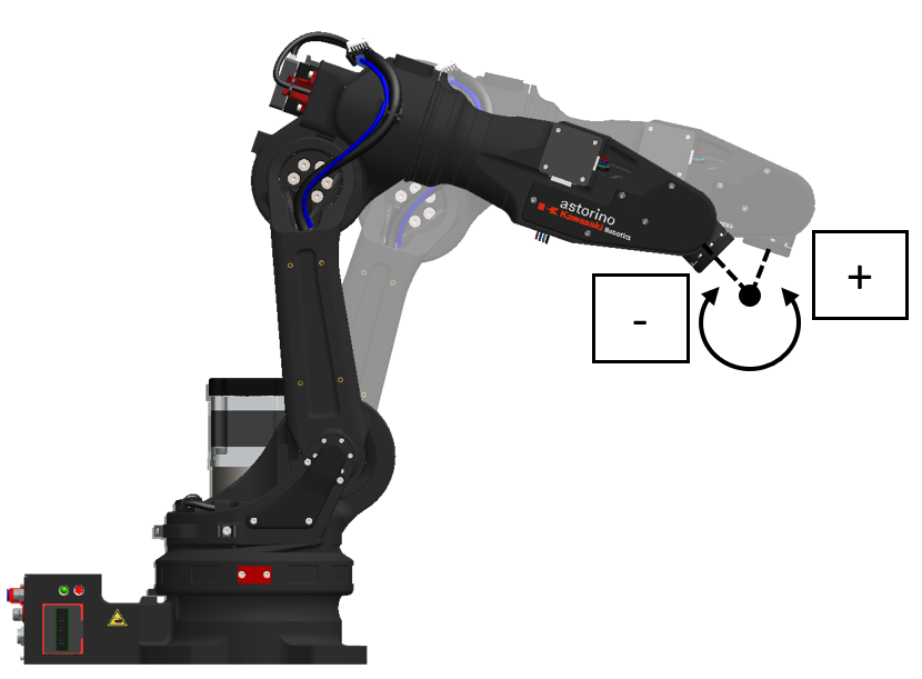
rz: Rotation around tool coordinate Z (TCP does not move)
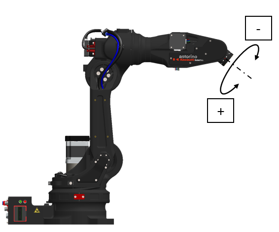
Repeat Mode – Repeating Programmed Movements
After programming and testing are complete, the robot can operate in Repeat mode – an automatic playback of previously recorded movements.
In this mode, speeds are not limited, and the robot can move at a maximum speed of 250 mm/s. The robot executes the program autonomously, without operator involvement.
- All trajectories, speeds, and commands are executed according to the stored program.
- Repeat mode is used in mass production, where precision, speed, and repeatability matter.
- The operator cannot manually control the robot in this mode; switching modes is required.
- Most robot programs are executed in repetitive cycles. The robot speed in teach mode is set separately from the speed in repeat mode.
In the Astorino robot, repeat mode allows full automation of processes such as part stacking, component testing, or visual inspection – everything depends on the programmed task.
5. Basic AS Language Commands
AS language is an industrial robot programming language developed by Kawasaki. Astorino is based on the AS language, with a few simplifications, but most commands remain the same. This makes it easy to transition from programming the Astorino to programming Kawasaki Robotics robots or other industrial robots.
The Astorino robot can be programmed either using the teach pendant or through the dedicated application. Both approaches have their advantages and disadvantages.
- Programming using the teach pendant:
- It is good for quick, minor changes, such as moving the robot to a new point and overwriting it,
- The teach pendant is always with the robot and does not require additional equipment,
- Writing more complex programs will be slower and less convenient than using a dedicated environment.
- Programming using the Astorino environment:
- It is very convenient as it provides easy access to all information, including stored tools, points, and I/O states.
- It allows program creation using a computer keyboard, facilitating fast code writing. Additionally, the environment provides a simulation of the robot.
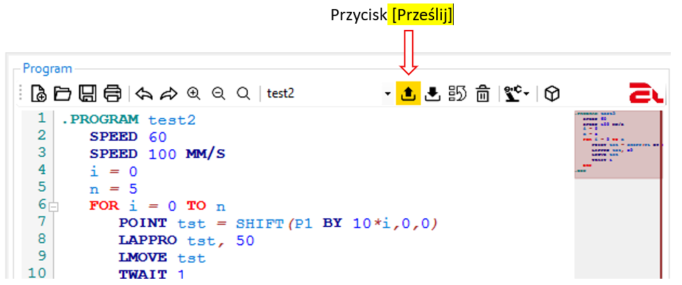
- It requires constant communication between the computer and the robot, e.g., via USB, and resynchronizing the files with the robot after program changes.
It should be noted that both methods are worth learning, but for writing complex programs, the Astorino software on a PC or laptop is definitely more convenient.
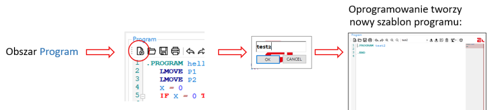
The following section explains how to create a program using the Astorino software. Detailed programming elements will be covered in the second part.
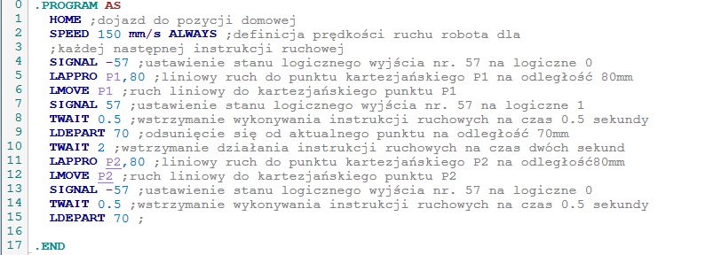
Sample program in AS language
Every program in AS language begins with .PROGRAM program_name and ends with .END. This defines where the program to be executed by the robot is located.
Comments
AS language also allows writing comments – lines of text that are not robot commands but are intended for the programmer. Comments help describe the program’s operation so operators know what the robot will do. To start a comment, use the character ;.
Types of Instructions in a Program
Instructions in a program can be divided into two types: those that cause robot movement and those that do not (e.g., those that set signals).
Motion Commands
Motion commands include, for example, LMOVE, JMOVE, LAPPRO, JAPPRO, HOME. Each of these commands (except HOME) takes a point in the robot’s working space as an argument. These points can be either Cartesian (X, Y, Z, RX, RY, RZ) or joint coordinates (J1, J2, J3, J4, J5, J6).
It should be remembered that joint points are referenced using the # character preceding the point name, e.g., #P1, #P5. Cartesian points can be referenced without the #, i.e.: P1, P5. It should be noted that these points are not equivalent. If the robot is taught point P1, moving to point #P1 without previously defining it may cause a program error; thus P1 and #P1 can refer to two completely different locations in space.
For the LAPPRO, JAPPRO commands, in addition to the point, a second argument must be provided: the distance in millimeters. The robot will approach the target point and stop at the specified distance from it along the tool’s Z-axis. Depending on the command, linear or joint interpolation can be used. This motion is very useful for pre-positioning the robot at a certain distance from the target and then calling a linear motion toward the target.
The LDEPART and JDEPART commands work very similarly, except that they do not take a target point as an argument. Instead, they only require the distance by which the robot should retreat from its current TCP position. It should be noted that when the robot is already positioned at a specified point, for example P1, executing the command LAPPRO P1, 50 will have exactly the same effect as LDEPART 50. In both cases, the robot will move away from point P1 by 50 millimeters along a linear trajectory.
Another type of AS language command is one that does not cause robot motion. These include, among others, SPEED, SIGNAL, TWAIT.
By default, the SPEED command sets the execution speed of the next motion command. A value can be specified in millimeters per second or as a percentage ranging from 0.01% to 100%. For example, “SPEED 100” sets the speed of the next movement to 100%, while “SPEED 150 MM/S” sets the speed of the next movement to 150 millimeters per second. It should be noted that the specified speed is not always achievable, for example when the distance between points is too small.
If every movement in the program should be performed at a constant speed, the command is “SPEED value in percent or mm/s ALWAYS”. Adding the word ALWAYS at the end causes the set speed to be applied to all subsequent motion commands until a new speed is defined (this may apply either to a single motion instruction or globally when using the ALWAYS parameter).
Another very important command is SIGNAL. This command is used to set the logical state of an output signal. The Astorino version B has eight independent outputs (plus two reserved for the tool) that can be used to control external devices. By default, output number 57 is assigned to the gripper, but Astorino can also control, e.g., a conveyor, actuators, or LEDs.
This allows us to include commands in the written program that enable control of such peripherals. Each of these signals can take two logical states:
- High state – logical true; usually means applying high voltage to the given output,
The syntax of the SIGNAL command is as follows: “SIGNAL signal number”. Thus, using “SIGNAL 57” sets output 57 HIGH, thereby closing the gripper. To set a low logic state, the signal number must be preceded by a minus sign; therefore, “SIGNAL -57” will open the gripper. The SIGNAL command can accept multiple arguments simultaneously. Multiple signals can be set simultaneously, e.g. “SIGNAL 1, 2, 5” sets signals 1, 2, and 5 to a high logic state, while “SIGNAL 2, -4, -6” sets output 2 to a high state and outputs 4 and 6 to a low state.
Another important command is TWAIT. It causes the program to pause for a specified time expressed in seconds. This can be extremely useful when controlling the gripper. Simply setting the signal state to high closes the gripper, but it needs time to physically close. The purpose is to prevent the robot from executing the next motion command, e.g., before the gripper has fully closed.
Astorino has many more useful commands that can be found in the AS language documentation at www.astorino.com.pl in the Files section, after logging in.
Programming using the teach pendant
The situation is slightly different when programming using the teach pendant. The AS language syntax does not change, but to add and edit individual commands, dedicated buttons on the teach pendant keyboard must be used. The image below shows the program editing screen displayed on the teach pendant..
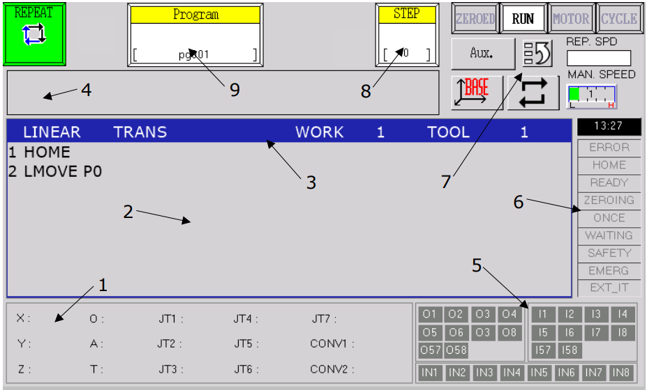
1. Current robot position
2. Program display area
3. Program instruction component selection bar
4. Message display window
5. I/O – inputs and outputs
6. Programming screen controls
7. Robot status controls and function buttons
8. Currently executed program step
9. Program management block
Teaching Points on the Teach Pendant
The basic task is teaching points. When the robot’s TCP reaches the specified position, this point should be saved in one of two ways.
The first method is to open the terminal (MENU button on the teach pendant keyboard) and enter the command HERE point name.
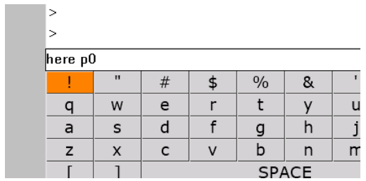
This way, both Cartesian and joint coordinates can be saved using the # sign.
Another way to teach the robot a point is to go to the menu AUX -> 5. Points.
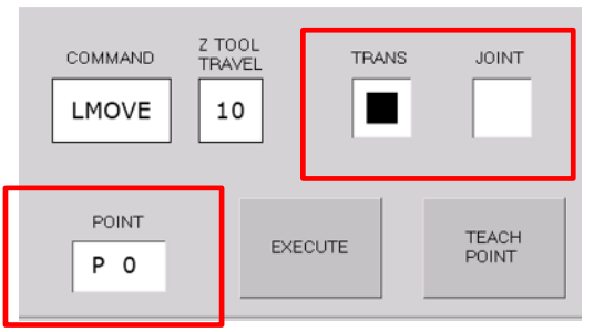
In the POINT field, enter the point number and specify whether it is a Cartesian point (TRANS) or a joint point (JOINT). The TEACH POINT button saves the robot’s current position as the specified point.
From the same window, motion to the specified point can be triggered. The motion type is set in the COMMAND field. When selecting the LAPPRO command, the offset distance can be specified in the Z TOOL TRAVEL field. Pressing the EXECUTE button while holding the deadman switch causes the robot to move to the specified point.
After teaching the robot the selected points, commands can be entered in the program editing window. To add a command, select the required one by pressing the A + INTERP button combination, which scrolls through available commands in the top blue bar. Once the needed command is found, simply press the REC button, which adds it at the end of the current program. To insert a line above the currently selected command, press A + INS. A selected line of code can be edited by pressing A + TOOL.
With the AS language elements introduced above, writing a similar program using the teach pendant should be straightforward.
6. Starting the Robot and the Software
To start the Astorino robot, switch on the main power supply and the robot controller using either the software or the control panel.
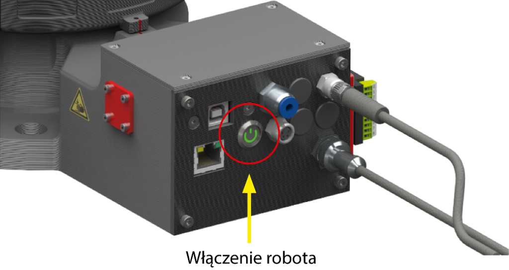
After starting the robot, it can be switched to manual or automatic mode and an appropriate program loaded. Before starting work, it is worth performing a test motion at low speed to ensure the trajectory is correct and safe. It should also be checked that the robot is in a safe starting position and that all system elements are operational.
Electrical connection of the Astorino robot:
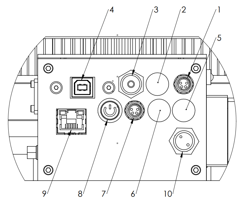
| 1. | M8 4-pin socket – external emergency switch (E-Stop) |
| 2. | External emergency switch SAFETY-FENCE (OPTION) |
| 3. | Pneumatic inlet Ø4.0 mm |
| 4. | USB-B port |
| 5. | OPTION 2 (encoder 2 – conveyor belt 2/JT7) |
| 6. | OPTION 1 (encoder 1 – conveyor belt 1) |
| 7. | Vision system/Serial communication (Pins: 1-GND, 2 – 5 V [Vision], 3-TX, 4-RX) |
| 8. | ON/OFF switch |
| 9. | Ethernet port (RJ45) |
| 10. | Power connector |
After installing the Astorino software, the robot must be prepared for operation. After launching the software, the COM port to which the robot is connected should automatically appear in the Connection drop-down list on the Control tab.
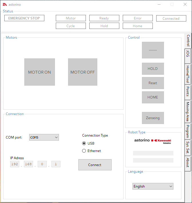
Then, after clicking [Reset], if the Reset button is highlighted in red, the Emergency Stop button should be checked.
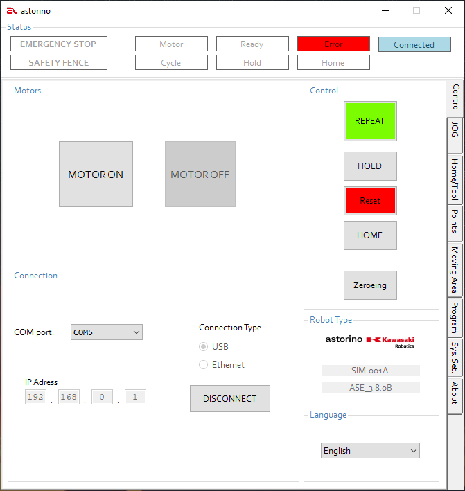
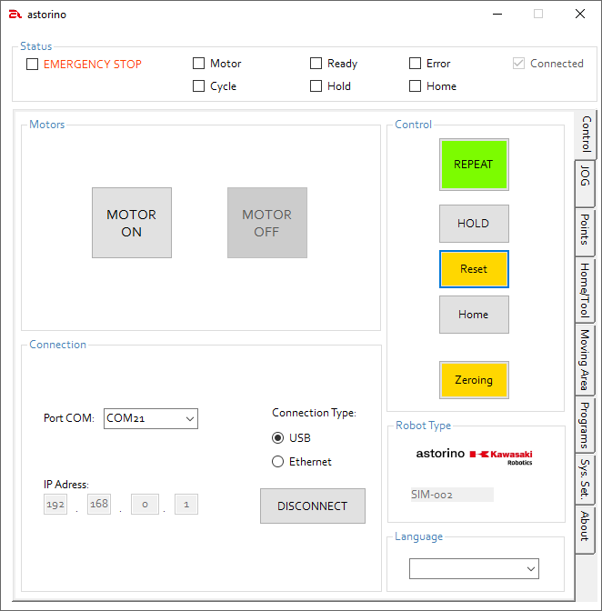
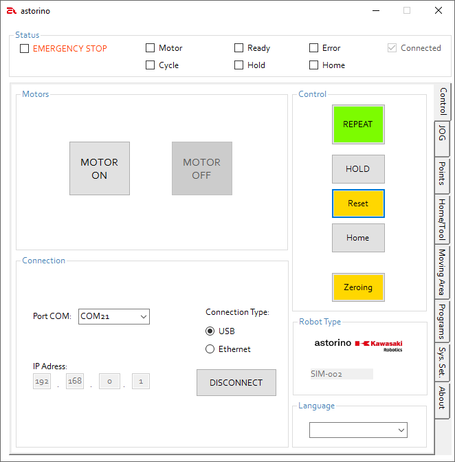
Enable the motors by clicking the grey button [MOTOR ON]. After clicking the yellow field [ZEROING], the zeroing process will begin. Zeroing must be performed every time the robot is disconnected from power or the motors are turned off. After zeroing is complete, the robot is ready for operation.
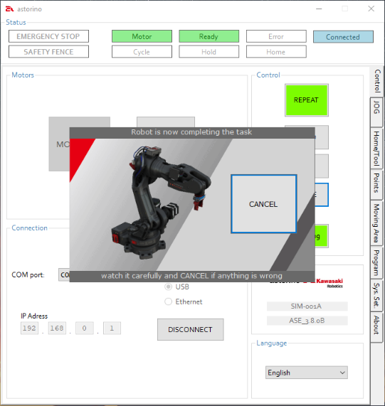
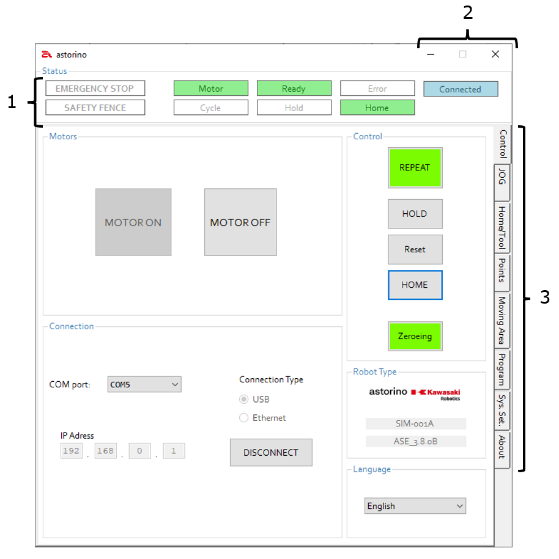
Basic Information about Astorino Robot Software
All data is stored on an internal microSD card located on the microcontroller board inside the robot’s base. If the robot is turned off, user data is not deleted.
| Main Window Overview | |
 1. Status 1. Status | Current status of the connected robot |
| 2. Control | Closing or minimizing the Astorino application |
| 3. Operation tabs | Switching between different operation tabs |
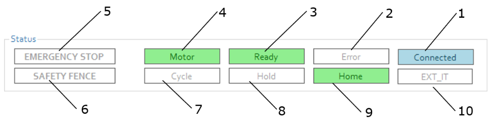
| Status Area | |
| 1. Connected | Connected to the Astorino software |
| 2. Error | An error has occurred |
| 3. Ready | If there is no emergency stop and no errors, drives are enabled and homing is complete |
| 4. Motors | Drives are enabled |
| 5. EMERGENCY STOP | Emergency stop is pressed and active |
| 6. SAFETY FENCE | Safety fence stop is active |
| 7. Cycle | Indicates that the program sequence is activated |
| 8. Hold | Indicates that the robot has been stopped |
| 9. Home | Indicates that the robot is at the home position |
| 10. EXT_IT | The robot has been stopped by an external signal |
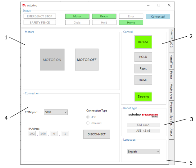
| Control Tab | ||
1. MOTORS | Motor status and control | |
| 2. CONTROL | Control of operating mode, robot stop or return to home position, error confirmation, and homing | |
| 3. ROBOT-TYPE | Robot firmware version and serial number | |
| 4. Connection | Connection selection and interface configuration, establishing or disconnecting the connection | |
| 5. Language | Display language selection |
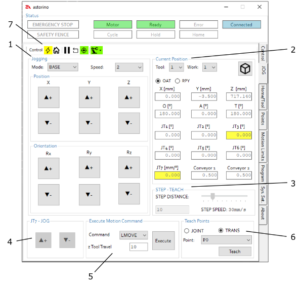
| JOG Tab | |
 1. Jogging 1. Jogging | Select motion mode and speed |
| 2. Current Position | Tool selection (Tool), display of angles*, current robot position |
| 3. STEP-TEACH | Set step size and step speed |
| 4. JT7 – JOG | Move the linear axis (JT7) – if available |
| 5. Execute Motion Command | Move to the selected point from the Teach Points section |
| 6. Teach Point | Select the point to teach or move to |
| 7. Control | Same functions as on the Control tab |
Creating a New Program
Loading a Program to the Robot
| For more detailed information, please refer to the “Astorino – User and Programming Manual”, available on the Astorino website https://astorino.com.pl/en/ in the Files section after logging in. |
Control Using the Teach Pendant
Another method of controlling the Astorino robot is manual control using the teach pendant. The Teach Pendant is a portable control panel that enables manual programming and operation of the Astorino robot. Using it, the operator can move the robot in manual mode, set trajectory points, edit programs, and run them in test mode.
The Teach Pendant is equipped with directional buttons, a display, and an Emergency Stop button, which ensures safety and precision during programming. After connecting to the robot, the operator should first become familiar with the buttons and keyboard.
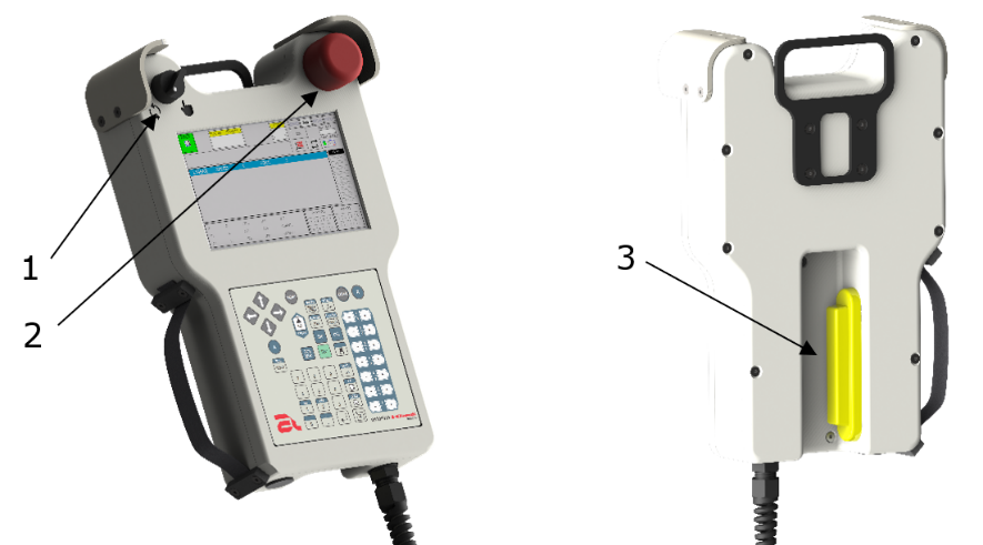
- TeachLock (Programmer Lock) – a two-position switch for changing the robot’s operating mode:
– TEACH operating mode

– REPEAT operating mode

2. Emergency Stop button
3. Deadman Switch (Enable Switch) – a three-position safety switch. Robot movement in TEACH mode is only possible when the switch is held in the middle position. The switch states are, respectively: OFF – ON – OFF.
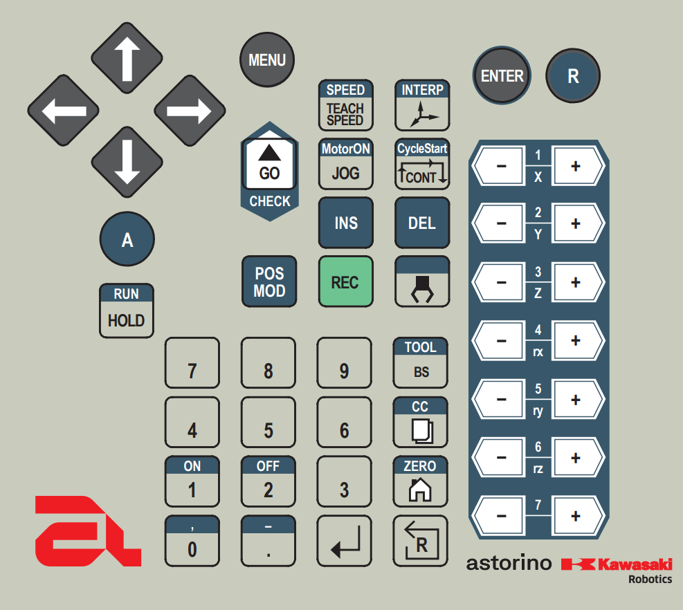
| Arrow keys | Navigation through screen options, scrolling through the program |
| MENU | Opening the quick-select menu |
| ENTER | Confirm selection |
| R | Return to the previous screen |
| A | ALT – activating additional button options |
| SPEED/TEACH SPEED | Changing the robot motion speed parameter in TEACH mode (+ALT) Changing the parameter of the instruction being added to the program |
| INTERP | Changing the robot motion mode in TEACH mode (+ALT) Changing the parameter of the motion instruction being added to the program |
| GO/CHECK | Execute the next instruction in STEP ONCE mode or run a single program line in Teach mode |
| MotorON/JOG | Enable/Disable robot drives (+ALT) Temporarily change robot speed in TEACH mode to value 5 |
| CycleStart/CONT | Change program execution continuity mode (+ALT) Start the robot work cycle from the currently selected line |
| INS | Add an instruction to the program above the currently selected line |
| DEL | (+ALT) Delete the currently selected program line |
| POS MOD | Change the position in the currently selected motion line, (+ALT) opens the text editor of the selected program line |
| REC | Add an instruction at the end of the program |
| Gripper | Enable signal 1 clamp and disable signal 2 clamp (gripper-dedicated signals) (+ALT) disable signal 1 and enable signal 2 |
| RUN/HOLD | Pause the currently executing work cycle (+ALT) Resume the work cycle |
| Numeric keyboard | Entering numeric values in the appropriate functions |
| ON | Enable the selected signal |
| OFF | Disable the selected signal |
| TOOL/BS | Backspace – delete the last character (+ALT) – change the selected tool |
| CC | N/A – not assigned |
| ZERO | Start the procedure for moving to the home position (+ALT) Start the zeroing procedure |
| Reset | Reset robot error |
| Confirm | Saves or confirms the settings |
| Axes (+/-) | Execute robot motion along the given axis (depending on the selected coordinate system) |
Details on the operation and individual screens of the teach pendant can be found in the document “Astorino Teach Pendant – User Manual”, available on the https://astorino.com.pl/en/ website in the Files section after logging in.
Check your knowledge
Open Questions:
1. What is the Astorino robot?
Answer: Astorino is an educational industrial robot designed for learning the basics of robotics, programming, and automation in schools and technical universities.
2. What safety measures are used when working with the Astorino robot?
Answer: Protective guards, emergency stops, speed limits, and low-speed teaching mode are used.
3. What is the teach pendant used for in the Astorino robot?
Answer: The teach pendant is used for manual robot control, setting positions, and creating and editing programs.
4. What movements can the Astorino robot perform?
Answer: Depending on the version, it can perform linear, rotational, and complex spatial trajectories.
5. What components can work with the Astorino robot?
Answer: It can work with grippers, sensors, vision cameras, conveyor belts, and other automation devices.
6. How does an industrial robot differ from an educational robot like Astorino?
Answer: An educational robot has a simplified structure, lower power, and is adapted for safe use in school conditions.
7. What skills does working with the Astorino robot develop?
Answer: Working with the robot develops technical, programming, logical, analytical, and occupational safety skills.
8. What does it mean that the Astorino robot has several degrees of freedom?
Answer: It means that its arm can move in several independent directions, increasing its range of motion and operational capabilities.
9. What are the limitations of the Astorino robot compared to large industrial robots?
Answer: Astorino has a smaller reach, payload, and power, but its functionality in terms of teaching is very similar.
10. What are example tasks that can be performed on the Astorino robot?
Answer: Transferring objects, palletizing, sorting, component assembly, and operation of test stations.
Test Questions:
Multiple Choice Test – Basic Level
1. What type of robot is Astorino?
A) a tracked mobile robot
B) an educational industrial robot
C) an inspection drone
D) an underwater inspection robot
2. What is the teach pendant used for?
A) for printing documents
B) for manual robot control
C) for charging the robot’s battery
D) for storing tools
3. What should be done before starting the Astorino robot?
A) check technical condition and safety, and perform robot zeroing
B) turn on relaxing music
C) print a report from the last program
D) manually lubricate the motors.
4. What is the name of the button used to immediately stop the robot?
A) Start
B) Reset
C) Emergency Stop
D) Exit
5. How many axes can an industrial robot have?
A) 2
B) 4
C) 5
D) 6
6. What does Teach mode mean in the Astorino robot?
A) automatic program execution
B) self-repair of the robot
C) manual position setting
D) cleaning the gripper
7. What determines the reach of the Astorino robot?
A) the number of screws
B) the mechanical structure and arm length
C) the color of wires
D) ambient temperature
8. When should low speed mode be used?
A) during robot transport
B) during vacation
C) during testing of new trajectories
D) when the robot is not connected
III. PRACTICAL EXERCISES – BASICS OF WORKING WITH THE ASTORINO ROBOT
Example 1. Motion Mode – BASE Coordinate System
Open the JOG tab and select the BASE coordinate system.
Control the robot and move it to various positions.
- Button control: Press “▲+” and “▼-” to move the robot
in BASE mode: X, Y, Z, RX, RY, RZ - Control the robot at various SPEED settings.
- For each degree of freedom, determine the critical points.
- Position the robot in various positions – pay attention to precision and speed.
- Place cube-shaped objects in various places and control the robot to position it above the object – start from the lowest speed and increase to maximum.
- Place several objects in different positions (tower) e.g., from 3 objects and control the robot to position it above the object – start from the lowest speed and increase to maximum.
Example 2. Motion Mode – JOINT Coordinate System
Open the JOG tab and select the BASE coordinate system.
- Control the robot and move it to various positions
Press “▲+” and “▼-” to move the robot along JOINT axes JT1..6 - Control the robot at various SPEED settings.
- For each degree of freedom, determine the critical points.
- Check the POINT tab to review the defined points of the robot’s set position.
- Position the robot in various positions – pay attention to precision and speed.
- Place cube-shaped objects in various places and control the robot so as to position it above the object – start from the lowest speed and increase to maximum.
- Place several objects in different positions (tower) e.g., from 3 objects and control the robot so as to position it above the object – start from the lowest speed and increase to maximum.
Example 3. Setting Robot Control Points
- Open the POINT tab and review it.
- Set several robot motion points.
- Teach the robot a specified sequence of movements at a given point P….
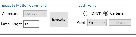
- Define your own robot position point and your own motion sequence, then execute it – at various speeds.
Example 4. Setting Robot Control Points – Sequences
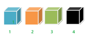
- Open the POINT tab and review it.
- Arrange elements according to the element placement diagram.
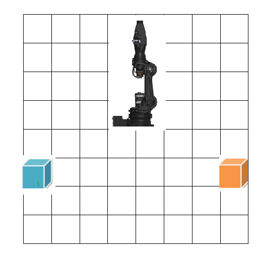
- Set robot points so that it moves to object no. 1 and then to object no. 2.
- Test point A at various speeds.
- Set robot points so that it moves to object no. 1, then to object no. 2, and back to object no. 1.
- Test point A at various speeds.
- Set robot points so that it moves to object no. 1, then to the HOME position, then to object no. 2, and then back to the HOME position.
- Test point A at various speeds.
Example 5. Setting Robot Control Points – Advanced Sequences
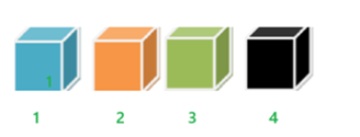
- Open the POINT tab and review it.
- Arrange objects according to the object placement diagram.
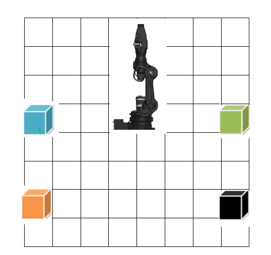
- Set robot points so that it moves to object no. 1, then to object no. 2, then to object no. 3, then to object no. 4.
- Test point A at various speeds.
- Set robot points so that it moves to objects 1, 2, 3, or 4 using different motion sequences.
- Test point C at various speeds.
Example 6. Gripper Control – Control Program
In this textbook, the author does not present the programming language itself, but focuses only on transcribing a sample program and modifying its parameters.
- Set point P1
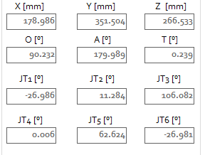
- Set point P2
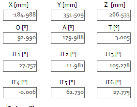
- Transcribe the sample program and load it into the robot’s RAM.
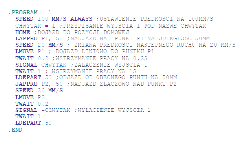
You can attempt to change points, add more, analyze the program, and add sequences.
Example 7. Manual Robot Control
Connect the teach pendant and then control the robot manually, first moving the robot to various points. Then, following the examples above or your own ideas, you can develop motion sequences and move objects. You can also try to transcribe the program included in this textbook using the teach pendant.
Index
HOME, 7, 32, 45, 64
Manipulator, 7, 11
Robot Environment, 7
Pedipulator, 7
Robot Joint, 7
Cartesian Point, 7, 45, 48
Joint Point, 7, 45, 48
Singularities, 7, 30
Robot, 7, 8, 9, 13, 29, 30, 31, 32, 43, 45
Industrial Robot, 8, 13, 29
Robotics, 8
Industrial Robotics, 8
Degrees of Freedom of a Robot, 8, 11, 12, 13, 16, 26
TCP, 8, 27, 29, 30, 31, 32, 33, 35, 40, 42, 45, 47
Teach Pendant, 8, 10, 15, 17, 28, 38, 43, 46, 47, 48, 55, 58
Control System, 8
Coming Soon:
| Volume II Intermediate Level Robot Programming Fundamentals Using the Astorino Robot |
| Volume III Advanced Level Integration of the Astorino Robot with Peripheral Devices |


Marek Niewiadomski, designer of Astorino robots:
Robotics is becoming increasingly accessible to everyone. Once associated mainly with the automotive industry and higher education, it is now becoming common even in small local manufacturing companies, and learning starts already in vocational and secondary schools. Astorino is a step toward the future and makes it easier for young, talented engineers to get an early start in this field. A start that is no longer just a theoretical introduction but real, practice-based learning.